RTL modeling
Introduction
RTL (Register Transfer Level) is a modeling abstraction level that is typically used to write synthesizable models. Synthesis refers to the process by which an HDL description is automatically compiled into an implementation for an ASIC or FPGA. This chapter describes how MyHDL supports it.
Combinatorial logic
Template
Combinatorial logic is described with a code pattern as follows:
from myhdl import block, always_comb

@block
def top(<parameters>):
    ...
    @always_comb
    def comb_logic():
        <functional code>
    ...
    return comb_logic, ...
The always_comb decorator describes combinatorial logic. The name refers
to a similar construct in SystemVerilog. The decorated function is a local
function that specifies what happens when one of the input signals of the logic
changes. The always_comb decorator infers the input signals
automatically. It returns a generator that is sensitive to all inputs, and that
executes the function whenever an input changes.
Example
The following is an example of a combinatorial multiplexer
from myhdl import block, always_comb, Signal

@block
def mux(z, a, b, sel):

    """ Multiplexer.

    z -- mux output
    a, b -- data inputs
    sel -- control input: select a if asserted, otherwise b

    """

    @always_comb
    def comb():
        if sel == 1:
            z.next = a
        else:
            z.next = b

    return comb
To verify it, we will simulate the logic with some random patterns. The
random module in Python’s standard library comes in handy for such purposes.
The function randrange(n) returns a random natural integer smaller than n.
It is used in the test bench code to produce random input values.
import random
from myhdl import block, instance, Signal, intbv, delay
from mux import mux

random.seed(5)
randrange = random.randrange

@block
def test_mux():

    z, a, b, sel = [Signal(intbv(0)) for i in range(4)]

    mux_1 = mux(z, a, b, sel)

    @instance
    def stimulus():
        print("z a b sel")
        for i in range(12):
            a.next, b.next, sel.next = randrange(8), randrange(8), randrange(2)
            yield delay(10)
            print("%s %s %s %s" % (z, a, b, sel))

    return mux_1, stimulus

tb = test_mux()
tb.run_sim()
It is often useful to keep the random values reproducible. This can be accomplished by providing a seed value as in the code. The run produces the following output:
$ python test_mux.py
z a b sel
5 4 5 0
3 7 3 0
2 2 1 1
7 7 3 1
3 1 3 0
3 3 6 1
6 2 6 0
1 1 2 1
2 2 2 0
3 0 3 0
2 2 2 1
3 5 3 0
<class 'myhdl.StopSimulation'>: No more events
Sequential logic
Template
Sequential RTL models are sensitive to a clock edge. In addition, they may be
sensitive to a reset signal. The always_seq decorator supports this
model directly:
from myhdl import block, always_seq

@block
def top(<parameters>, clock, ..., reset, ...):
    ...
    @always_seq(clock.posedge, reset=reset)
    def seq_logic():
        <functional code>
    ...
    return seq_logic, ...
The always_seq decorator automatically infers the reset
functionality. It detects which signals need to be reset, and uses their
initial values as the reset values. The reset signal itself needs to be
specified as a ResetSignal object. For example:
reset = ResetSignal(0, active=0, isasync=True)
The first parameter specifies the initial value. The active parameter
specifies the value on which the reset is active, and the isasync
parameter specifies whether it is an asychronous (True) or a
synchronous (False) reset. If no reset is needed, you can assign
None to the reset parameter in the always_seq parameter.
Example
The following code is a description of an incrementer with enable, and an asynchronous reset.
from myhdl import block, always_seq

@block
def inc(count, enable, clock, reset):
    """ Incrementer with enable.

    count -- output
    enable -- control input, increment when 1
    clock -- clock input
    reset -- asynchronous reset input
    """

    @always_seq(clock.posedge, reset=reset)
    def seq():
        if enable:
            count.next = count + 1

    return seq
For the test bench, we will use an independent clock generator, stimulus
generator, and monitor. After applying enough stimulus patterns, we can raise
the StopSimulation exception to stop the simulation run. The test bench for
a small incrementer and a small number of patterns is a follows
import random
from myhdl import block, always, instance, Signal, \
    ResetSignal, modbv, delay, StopSimulation
from inc import inc

random.seed(1)
randrange = random.randrange

ACTIVE_LOW, INACTIVE_HIGH = 0, 1

@block
def testbench():
    m = 3
    count = Signal(modbv(0)[m:])
    enable = Signal(bool(0))
    clock  = Signal(bool(0))
    reset = ResetSignal(0, active=0, isasync=True)

    inc_1 = inc(count, enable, clock, reset)

    HALF_PERIOD = delay(10)

    @always(HALF_PERIOD)
    def clockGen():
        clock.next = not clock

    @instance
    def stimulus():
        reset.next = ACTIVE_LOW
        yield clock.negedge
        reset.next = INACTIVE_HIGH
        for i in range(16):
            enable.next = min(1, randrange(3))
            yield clock.negedge
        raise StopSimulation()

    @instance
    def monitor():
        print("enable  count")
        yield reset.posedge
        while 1:
            yield clock.posedge
            yield delay(1)
            print("   %s      %s" % (int(enable), count))

    return clockGen, stimulus, inc_1, monitor

tb = testbench()
tb.run_sim()
The simulation produces the following output
$ python test_inc.py
enable  count
   0      0
   1      1
   0      1
   1      2
   0      2
   1      3
   1      4
   1      5
   1      6
   1      7
   0      7
   0      7
   1      0
   0      0
   1      1
   1      2
Alternative template
The template with the always_seq decorator is convenient
as it infers the reset functionality automatically. Alternatively,
you can use a more explicit template as follows:
from myhdl import block, always

@block
def top(<parameters>, clock, ..., reset, ...):
    ...
    @always(clock.posedge, reset.negedge)
    def seq_logic():
       if not reset:
           <reset code>
       else:
           <functional code>

    return seq_logic,...
With this template, the reset values have to be specified explicitly.
Finite State Machine modeling
Finite State Machine (FSM) modeling is very common in RTL design and therefore deserves special attention.
For code clarity, the state values are typically represented by a set of identifiers. A standard Python idiom for this purpose is to assign a range of integers to a tuple of identifiers, like so
>>> SEARCH, CONFIRM, SYNC = range(3)
>>> CONFIRM
1
However, this technique has some drawbacks. Though it is clearly the intention that the identifiers belong together, this information is lost as soon as they are defined. Also, the identifiers evaluate to integers, whereas a string representation of the identifiers would be preferable. To solve these issues, we need an enumeration type.
MyHDL supports enumeration types by providing a function enum. The
arguments to enum are the string representations of the identifiers, and
its return value is an enumeration type. The identifiers are available as
attributes of the type. For example
>>> from myhdl import enum
>>> t_State = enum('SEARCH', 'CONFIRM', 'SYNC')
>>> t_State
<Enum: SEARCH, CONFIRM, SYNC>
>>> t_State.CONFIRM
CONFIRM
We can use this type to construct a state signal as follows:
state = Signal(t_State.SEARCH)
As an example, we will use a framing controller FSM. It is an imaginary
example, but similar control structures are often found in telecommunication
applications. Suppose that we need to find the Start Of Frame (SOF) position of
an incoming frame of bytes. A sync pattern detector continuously looks for a
framing pattern and indicates it to the FSM with a syncFlag signal. When
found, the FSM moves from the initial SEARCH state to the CONFIRM state.
When the syncFlag is confirmed on the expected position, the FSM declares
SYNC, otherwise it falls back to the SEARCH state. This FSM can be
coded as follows
from myhdl import block, always_seq, Signal, intbv, enum

ACTIVE_LOW = 0
FRAME_SIZE = 8
t_state = enum('SEARCH', 'CONFIRM', 'SYNC')

@block
def framer_ctrl(sof, state, sync_flag, clk, reset_n):

    """ Framing control FSM.

    sof -- start-of-frame output bit
    state -- FramerState output
    sync_flag -- sync pattern found indication input
    clk -- clock input
    reset_n -- active low reset

    """

    index = Signal(intbv(0, min=0, max=FRAME_SIZE)) # position in frame

    @always_seq(clk.posedge, reset=reset_n)
    def FSM():
        if reset_n == ACTIVE_LOW:
            sof.next = 0
            index.next = 0
            state.next = t_state.SEARCH

        else:
            index.next = (index + 1) % FRAME_SIZE
            sof.next = 0

            if state == t_state.SEARCH:
                index.next = 1
                if sync_flag:
                    state.next = t_state.CONFIRM

            elif state == t_state.CONFIRM:
                if index == 0:
                    if sync_flag:
                        state.next = t_state.SYNC
                    else:
                        state.next = t_state.SEARCH

            elif state == t_state.SYNC:
                if index == 0:
                    if not sync_flag:
                        state.next = t_state.SEARCH
                sof.next = (index == FRAME_SIZE-1)

            else:
                raise ValueError("Undefined state")

    return FSM
At this point, we will use the example to demonstrate the MyHDL support for waveform viewing. During simulation, signal changes can be written to a VCD output file. The VCD file can then be loaded and viewed in a waveform viewer tool such as gtkwave.
The user interface of this feature consists of a single function,
traceSignals. To explain how it works, recall that in MyHDL, an
instance is created by assigning the result of a function call to an instance
name. For example:
tb_fsm = testbench()
To enable VCD tracing, the instance should be created as follows instead:
tb_fsm = traceSignals(testbench)
Note that the first argument of traceSignals consists of the uncalled
function. By calling the function under its control, traceSignals
gathers information about the hierarchy and the signals to be traced. In
addition to a function argument, traceSignals accepts an arbitrary
number of non-keyword and keyword arguments that will be passed to the function
call.
A small test bench for our framing controller example, with signal tracing enabled, is shown below:
import myhdl
from myhdl import block, always, instance, Signal, ResetSignal, delay, StopSimulation
from fsm import framer_ctrl, t_state

ACTIVE_LOW = 0

@block
def testbench():

    sof = Signal(bool(0))
    sync_flag = Signal(bool(0))
    clk = Signal(bool(0))
    reset_n = ResetSignal(1, active=ACTIVE_LOW, isasync=True)
    state = Signal(t_state.SEARCH)

    frame_ctrl_0 = framer_ctrl(sof, state, sync_flag, clk, reset_n)

    @always(delay(10))
    def clkgen():
        clk.next = not clk

    @instance
    def stimulus():
        for i in range(3):
            yield clk.negedge
        for n in (12, 8, 8, 4):
            sync_flag.next = 1
            yield clk.negedge
            sync_flag.next = 0
            for i in range(n-1):
                yield clk.negedge
        raise StopSimulation()

    return frame_ctrl_0, clkgen, stimulus

tb = testbench()
tb.config_sim(trace=True)
tb.run_sim()
When we run the test bench, it generates a VCD file called
testbench.vcd. When we load this file into gtkwave, we can
view the waveforms:
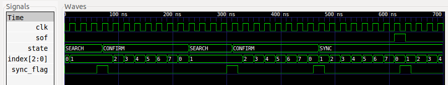
Signals are dumped in a suitable format. This format is inferred at the
Signal construction time, from the type of the initial value. In
particular, bool signals are dumped as single bits. (This only works
starting with Python 2.3, when bool has become a separate type).
Likewise, intbv signals with a defined bit width are dumped as bit
vectors. To support the general case, other types of signals are dumped as a
string representation, as returned by the standard str function.
Warning
Support for literal string representations is not part of the VCD standard. It is specific to gtkwave. To generate a standard VCD file, you need to use signals with a defined bit width only.